AI and OpenSCAD: Designing Physical Objects in Code
How I used an AI coding assistant to design a 3D-printable IoT enclosure. The workflow that emerged surprised me.
The setup
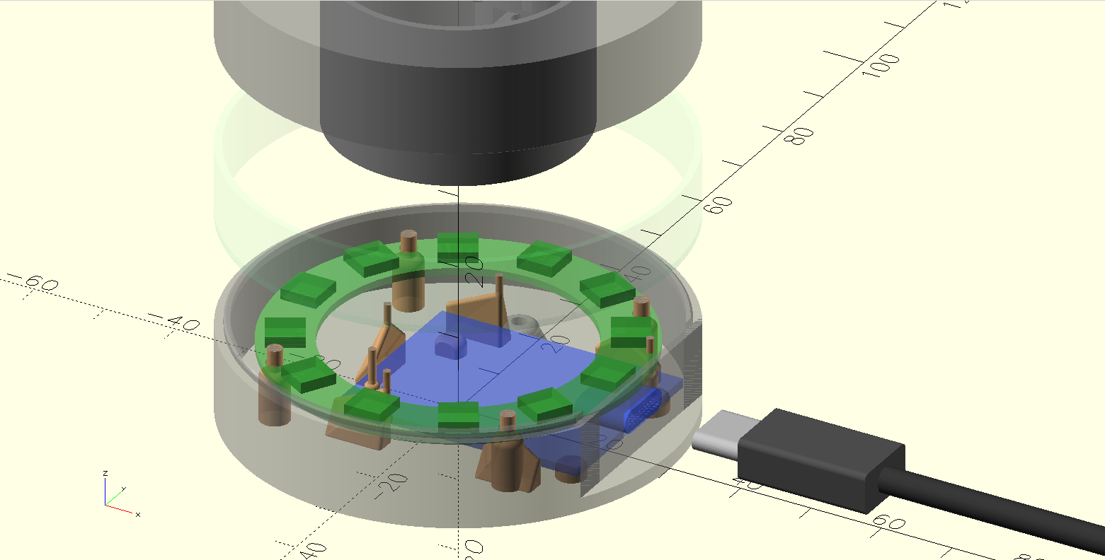
I needed a case for the Halo Terminal, a small IoT controller built around a D1 Mini ESP8266 and a 12-LED ring. Three-piece snap-together enclosure: base, ring, lid. About 60mm in diameter, 32mm tall, with a USB-C port cutout.
I chose OpenSCAD because it is code. No GUI, no click sequences, no proprietary file formats. Every dimension is a named variable. Every shape is a function call. The entire model is a program that compiles to geometry.
This turned out to be the decision that made AI collaboration possible.
Why OpenSCAD works with LLMs
Most CAD tools store their state in binary formats or complex GUI hierarchies. An AI can write a Fusion 360 macro, but it cannot look at an existing design and understand what it sees. It has no access to the spatial relationships, the constraints, the design intent.
OpenSCAD is different. The entire model is source code. Here is the central config file that defines the case dimensions:
// Case dimensions
diameter = 60;
wall_thickness = 2;
floor_thickness = 2;
top_thickness = 2;

// Section heights
base_height = 10 + floor_thickness;
middle_section_height = 10;
lid_height = 10 + top_thickness;
total_height = base_height + middle_section_height + lid_height;
An LLM can read this and understand that the case is cylindrical, 60mm across, with three sections that stack. It can trace derived values. It can propose changes and predict their consequences. This is the same kind of reasoning LLMs already do well with any codebase.
The real test: accommodating a hardware variant
The moment that convinced me this workflow has legs was not the initial design. It was when the hardware changed.
I had a D1 Mini variant with an additional chip soldered to the bottom of the PCB. 24mm long, 16mm wide, 3.1mm thick. The existing case did not have clearance for it.
I described the problem in plain language: "The only difference is that it has an additional chip on the bottom of the PCB. The end is aligned, the length is 24mm, width 16, thickness 3.1mm."
No drawings. No CAD sketches. Just dimensions and a verbal description.
The AI read the existing codebase: the PCB model, the standoff heights, the floor thickness, the USB port positioning. It traced how usb_wall_cutout_center_height determines standoff height, which determines clearance under the PCB. It calculated that the 3.1mm chip minus the 2.2mm standoff height left 0.9mm that needed accommodation.
Then it proposed raising the entire PCB to make room.
The human corrects the approach
I suggested something simpler: cut a pocket in the floor. Not through, just make part of it thinner where the chip sits.
The AI immediately recognized this was better. A floor pocket is a single localized change. Raising the PCB would cascade through the USB cutout height, the LED ring stand height, and several other derived dimensions. The pocket approach modifies one area without touching the rest of the design.
This is the pattern I kept seeing. The AI generates a solution that is correct but overcomplicated. The human, who has physical intuition about the part, redirects toward the cleaner approach. The AI then executes that approach well, tracing the change through every file that needs updating.
The feedback loop
The workflow settled into a rhythm:
1. I describe what needs to change. In natural language, with physical measurements. "Increase side clearance to 0.5." "The standoffs under the PCB are above the cutout of the chip. You should also cut them."
2. The AI edits the code. It finds the right variables, traces dependencies, updates all references. When I asked for different clearances on left and right sides (0.1mm and 0.6mm, so one print fits two board variants without separate STLs), it split a single side_clearance variable into side_clearance_left and side_clearance_right, updated every reference across multiple files, and recalculated derived values.
3. I look at the OpenSCAD preview. This is the step the AI cannot do. I see the 3D model rendered live, rotate it, check that things look right. When the chip was rendered the same color as the PCB and invisible, I said so. The AI made it red.
4. I test the physical fit. Print, try the part, measure. "Can we make different side clearance for left and right? I want left 0.1 and right 0.6." That decision came from wanting one print to fit two board variants. The AI can implement it in seconds, but the reasoning requires knowing what boards exist and what tradeoffs matter.
5. The AI exports STLs. It runs the export script, or invokes OpenSCAD directly with the right -D flags. Batch operations across all three parts.
What the AI handles well
Bookkeeping. When a variable name changes or a parameter splits into two, every reference across every file needs updating. Comments need to match the new behavior. This is tedious, error-prone work for a human and trivial for an LLM that can search the entire codebase.
Spatial reasoning from code. Given named variables and explicit formulas, the AI can trace geometric relationships. It understood that the light tube must clear the LED ring, that screw bosses need to align with floor holes, that the nut trap slot opens toward the inside of the case. All from reading the code.
Design-vs-manufacturing separation. When I said the exported lid should be rotated 180 degrees for printing, the AI added a lid_print_orientation toggle: false for the design view (normal orientation), true in the export script (flipped for the print bed). Clean separation of concerns.
Parametric consistency. OpenSCAD's parametric nature means a change to one value propagates correctly through derived dimensions. The AI understands this propagation and can predict consequences before making a change.
What the AI cannot do
See the result. The biggest limitation. Every spatial error required me to look at the preview, describe what was wrong, and explain how to fix it. If the AI could render the model and inspect it visually, half the iteration cycles would disappear.
Judge tolerances. The AI can implement any clearance value, but it cannot determine the right one. That comes from printing a test piece, trying the fit, and feeling whether 0.3mm is too tight or 0.5mm is too loose. Manufacturing knowledge is experiential.
Think about printability. Support structures, overhang angles, layer adhesion, thermal warping. The thin support pins in the model (1mm cylinders that extend to the top of the base section) exist to maintain consistent layer time during printing. That is the kind of manufacturing detail that only comes from experience with the printer.
// Support cylinder through tip to top of base section
// Prevents layer line artifacts during 3D printing
translate([back_wall_thickness - wall_radius, back_wall_length/2, 0])
    cylinder(h = full_height, d = 1, $fn = $fn_low);
Make design taste decisions. The peaked retention walls with rounded edges (built from hulled spheres) are a design choice. They look good and they print well. The AI would have generated simple rectangular walls unless told otherwise.
The interesting question
Most discussions about AI and CAD focus on generating geometry from text prompts. "Make me a phone case." That is a parlor trick. The geometry is the easy part.
The hard parts of physical design are tolerances, manufacturing constraints, assembly sequences, material behavior, and the thousand small decisions that make a part actually work when printed. These require physical feedback loops that currently only a human with a printer can close.
What works today is something more modest but genuinely useful: an AI that handles the code-level complexity of a parametric model while a human handles the physics. Neither is fast at the other's job. I would spend 30 minutes tracing every reference to side_clearance through the codebase. The AI would produce something that compiles but does not fit.
Together, we designed and iterated on a multi-part snap-fit enclosure in a single session. The final model is about 400 lines of OpenSCAD across 10 files. It compiles to three STL files that print and snap together on the first try.
What would change this
Visual feedback. If the AI could render the OpenSCAD model and inspect the result, the "I look at it and tell you what is wrong" step goes away. That alone would cut iteration time in half.
The pieces are close. Vision models can already interpret 3D renderings. OpenSCAD can render to PNG from the command line. Connecting these is an engineering task, not a research problem.
Until then, the workflow is: code goes to the AI, physics goes to the human. For parametric CAD, that split works better than I expected.
Stack
OpenSCAD, Claude Code, a Bambu Lab A1 mini printer, and PLA filament. No plugins, no cloud CAD, no special tooling. The model is plain text files in a git repo.
Written by Martin Sigloch with Tachikoma.
Get notified when I publish new posts.